PPPoE Dial-Up Configuration
This guide is for two common cases:
- home broadband PPPoE, where the Raspberry Pi soft router should dial directly
- campus or ISP environments where PPPoE works inconsistently, WiFi becomes unstable, or the wireless network disappears after boot
If your Raspberry Pi only connects to an upstream router through LAN, this is not your main path. Read LAN Connection first.
Understand the layout first
On a single-port Raspberry Pi, the biggest mistake is usually not the PPPoE username or password.
The real problem is mixing up LAN and WAN.
The correct design is:
- PPPoE lives only on the logical
WANside interface - the
LANinterface stays onbr-lan - the
br-lanbridge must be allowed to start even when it has no bridge ports yet
If you directly bind LAN to a wireless device or break the bridge relationship, common results include:
- AP attachment problems
br-lanfailing to start or starting in the wrong order- WiFi disappearing after boot
- clients joining WiFi but failing to reach the internet
So the real goal is not just “make PPPoE dial successfully”.
The real goal is “keep the LAN -> br-lan -> WiFi chain intact”.
Typical failure symptom
Campus networks and some ISP environments may show errors like this when dial-up fails:

Figure 1: Typical error screen when PPPoE dial-up fails.
Reference video:
Installing OpenWrt on Raspberry Pi as Main Router and Solving Campus Login Page Access Issues
Step 1: Create WAN0 and enter the PPPoE account
In Network -> Interfaces, create WAN0, choose protocol PPPoE, and enter the account and password provided by your ISP or campus network.
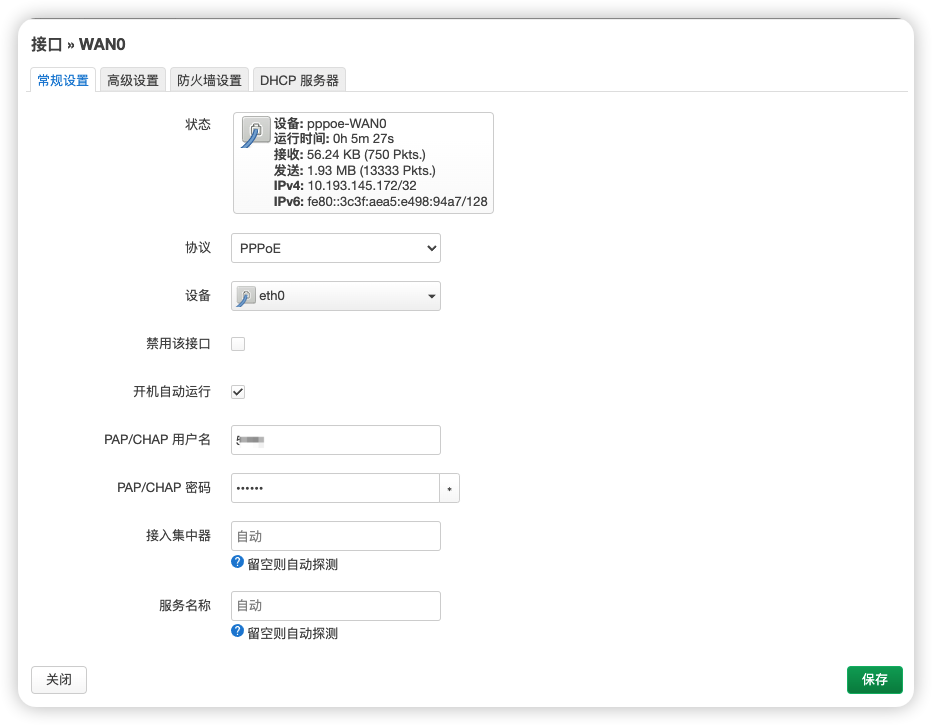
Figure 2: Create the WAN0 interface and set its protocol to PPPoE.
After that, the firewall zone for WAN0 must be wan.
If WAN0 is not placed in the wan firewall zone, the usual result is:
- the router itself dials successfully
- clients can still join WiFi
- but end devices cannot access the internet correctly
That happens because LAN -> WAN forwarding, NAT, and outbound policies all depend on the correct firewall zone.
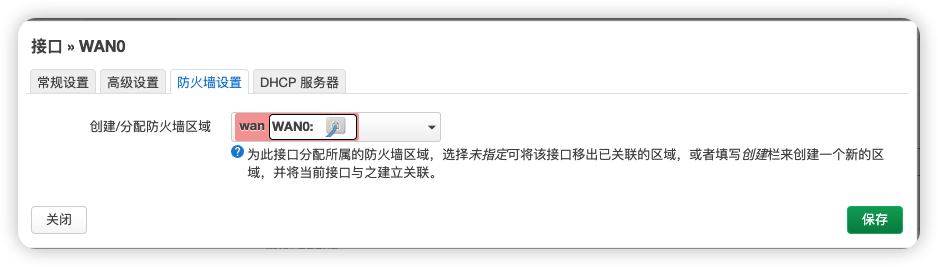
Figure 3: WAN0 should be assigned to the wan firewall zone.
Step 2: Keep the LAN interface on br-lan
Do not casually change the device bound to LAN.
It should remain:
Network device: "br-lan" (lan)
It should not be replaced with a wireless device, and it should not be tied directly to the PPPoE tunnel.
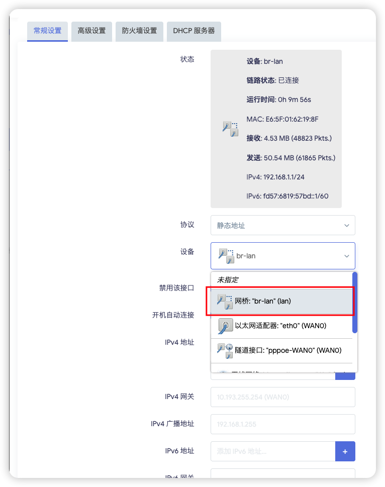
Figure 4: Keep the LAN interface bound to br-lan.
The wireless AP is supposed to attach to the LAN side bridge.
The design should not be reversed so that LAN depends on the wireless device itself.
The correct wireless binding example is shown in Step 5: Keep wireless networks attached to LAN.
If you incorrectly bind LAN to the wireless side, you create a dependency loop:
LANdepends on wireless- wireless also depends on
LAN / bridgeto exist properly
That often leads to unstable startup ordering and broken bridge state, such as:
- WiFi missing after boot
- SSID appearing inconsistently
- clients failing to obtain valid addresses
The following is the kind of configuration you should avoid:
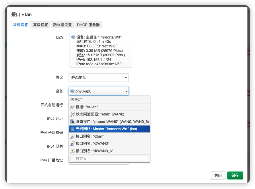
Figure 5: Wrong example. Do not change the LAN device to a wireless device or another incorrect interface.
Step 3: Keep the LAN firewall zone as lan
The LAN interface should remain in the lan firewall zone and should not be mixed into wan.
If this is wrong, common symptoms are:
- WiFi clients can connect but routing behaves incorrectly
- DHCP or local access becomes unstable
- LAN/WAN boundaries become unclear

Figure 6: Keep the LAN interface inside the lan firewall zone.
Step 4: Configure the br-lan bridge device
This is the part many users miss.
Go to Network -> Interfaces -> Devices, find br-lan, and click Configure.
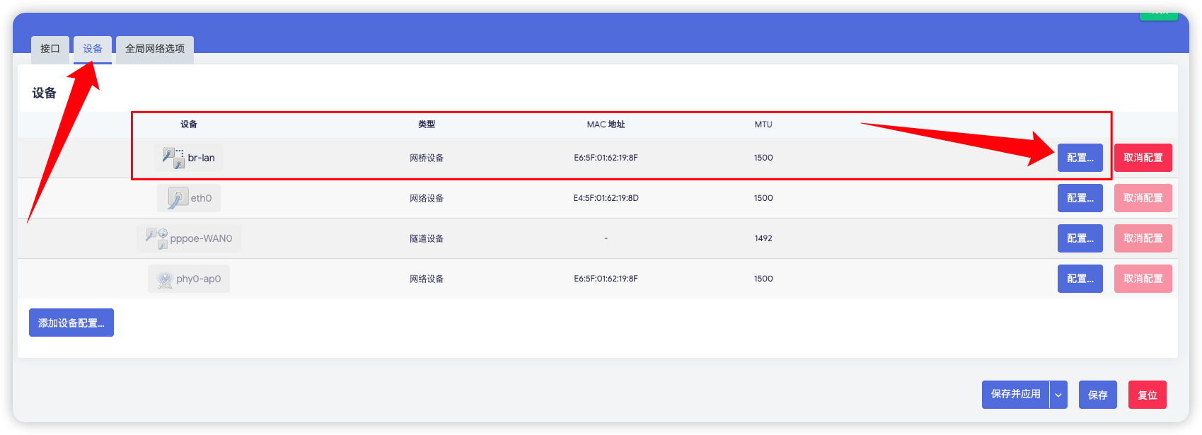
Figure 7: Open the br-lan device configuration page from the Devices tab.
In the br-lan configuration page, leave Bridge ports empty.
Do not force eth0, pppoe-WAN0, or other devices into that list.
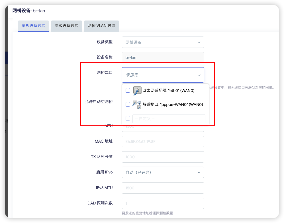
Figure 8: Leave the br-lan bridge ports empty.
This setting describes the membership of the bridge device itself.
If you incorrectly add WAN-side devices or the PPPoE tunnel here, you blur the separation between LAN and WAN.
At the same time, enable “Bring up empty bridge”.
It allows br-lan to start even when it does not yet have bridge members at that moment.
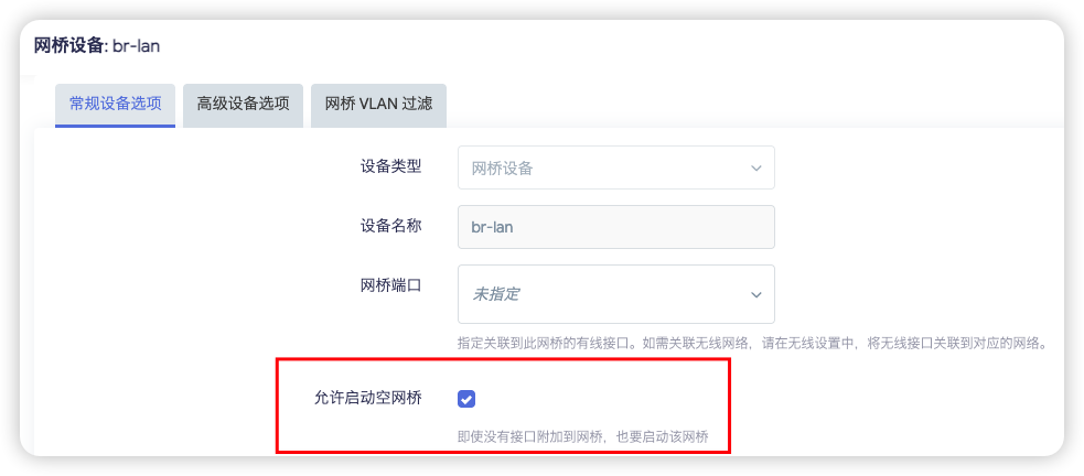
Figure 9: Enable “Bring up empty bridge” so br-lan can start even when the bridge is temporarily empty.
If you leave it disabled, some boot sequences may cause:
br-lannot starting in time- the wireless AP failing to attach correctly
- WiFi disappearing or failing to broadcast after reboot
Step 5: Keep wireless networks attached to LAN
If you added one or more wireless configurations, whether they are the main SSID or extra SSIDs, they should still be attached to lan, not to WAN0.
First go to Network -> Wireless and edit the wireless configuration you want to keep on the LAN side.
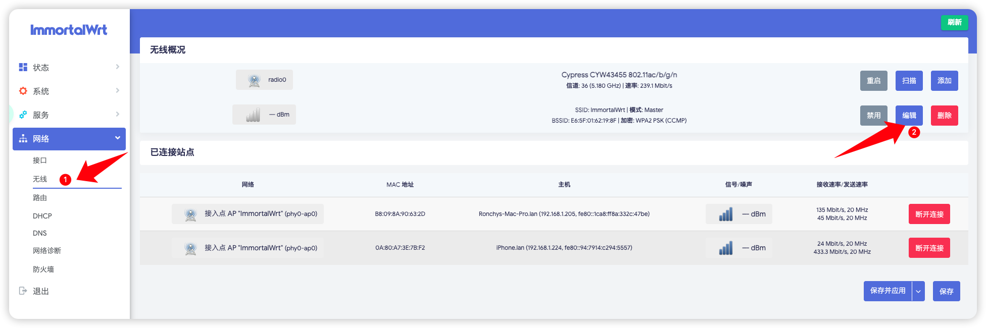
Figure 10: Open the wireless configuration from the Wireless page.
Then set the wireless interface Network field to lan, not WAN0.
If you added two wireless configurations, apply the same rule to both.
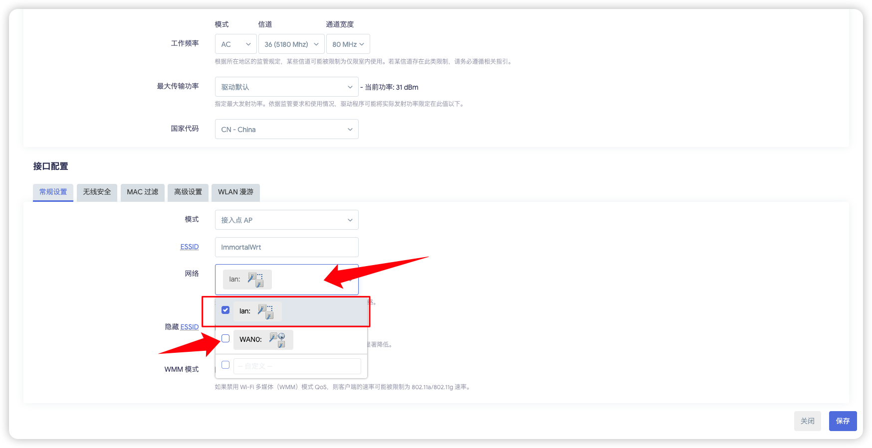
Figure 11: Bind the wireless interface to lan, not WAN0.
The reason is straightforward:
- a wireless AP belongs to the internal access side
WAN0is the external dial-up side- binding wireless to
WAN0pushes client access onto the wrong side of the firewall and routing model
Step 6: Save and verify the final state
After applying the configuration, go back to the interface overview.
The ideal result is:
lanstill exists and still usesbr-lanWAN0 / pppoe-WAN0dials successfully- WiFi broadcasts normally
- clients can connect and access the internet
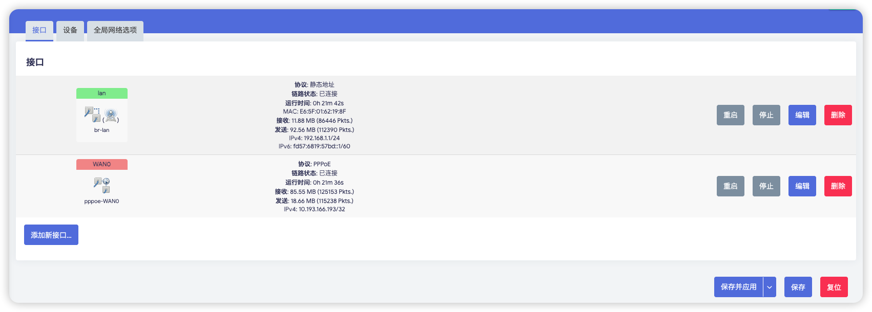
Figure 12: Final correct state after configuration, with clear separation between LAN and WAN0.
Common checks
Treat these as symptom-based checks, not as separate chapters.
- WiFi disappears after boot.
Check these first:
-
whether the
LANdevice is stillbr-lan -
whether the
br-lanbridge ports are still empty -
whether “Bring up empty bridge” is enabled
-
WiFi works, but there is no internet.
Check these first:
-
whether
WAN0really dialed successfully -
whether
WAN0belongs to thewanfirewall zone -
whether
LANstill belongs to thelanfirewall zone -
It works on macOS but not on Windows, or the reverse.
Before suspecting PPPoE itself, check client-side network priority.
macOS: move WiFi to a higher network priorityWindows: disconnect Ethernet and test with WiFi only
Otherwise the client may still be preferring another NIC, which makes it look like the router configuration is wrong.
Done
At this point, the Raspberry Pi can operate as the main PPPoE router, and clients connected to its WiFi should be able to reach the internet normally.